From human, to machine, to human, we designed a process that retained the designer's hand throughout digital fabrication. A collection of software tools were used including Rhino, Grasshopper and Processing.
1. Hand Drawing
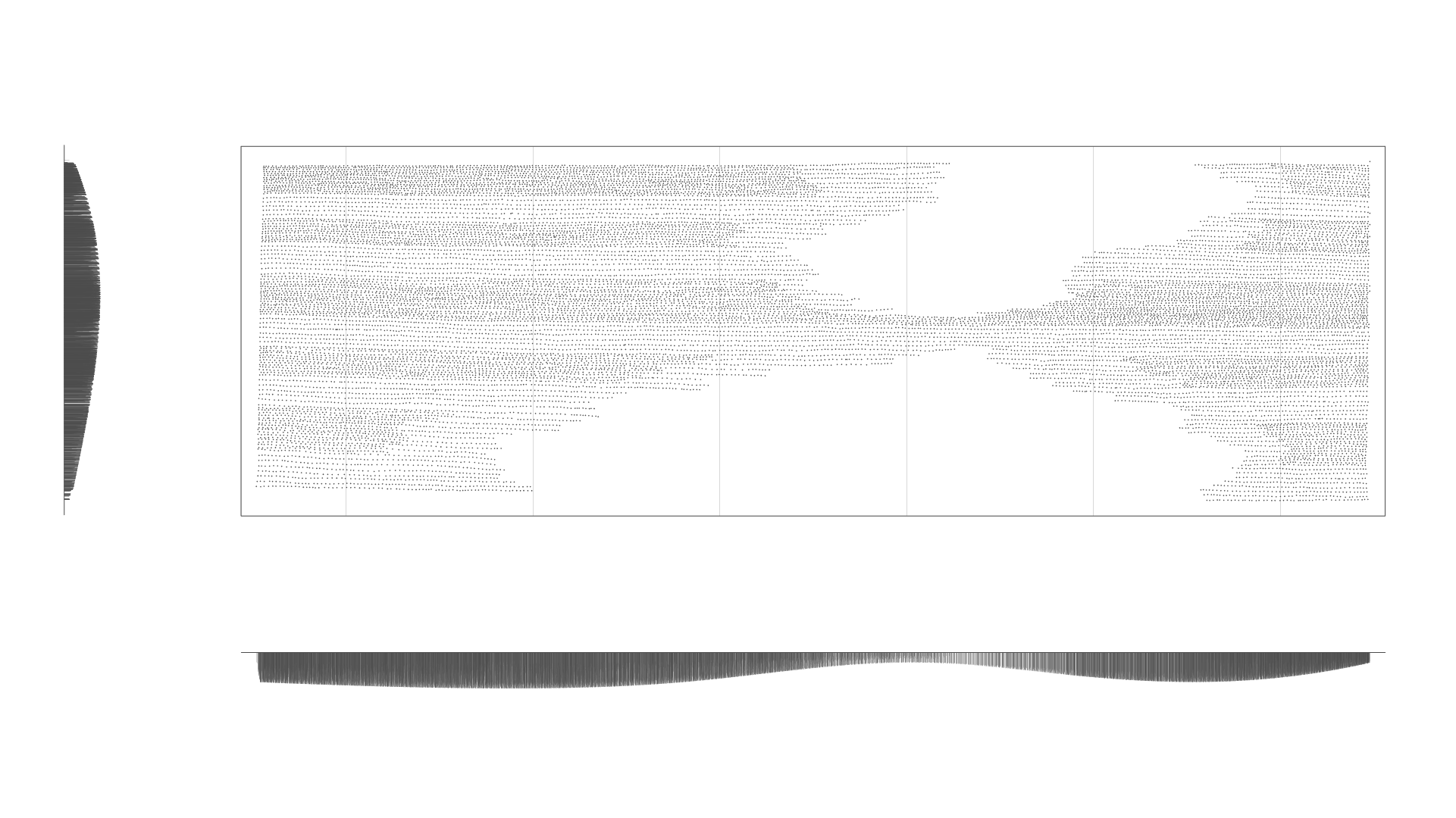
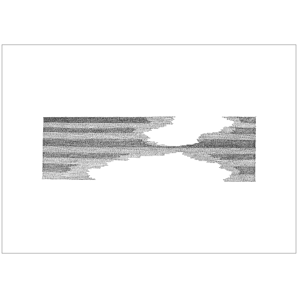
Grace created a 9" x 15" drawing using ink on paper. 20,092 ink dots were laid down over a 5 hour period.
2. Scan & Locate Dots
We scanned the drawing and wrote a Processing script to process it. The script found the ink blobs and determined the centroid of each blob. The centroid data was exported to a CSV file to use in Grasshopper.
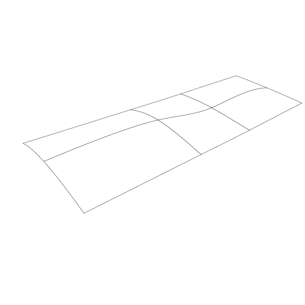
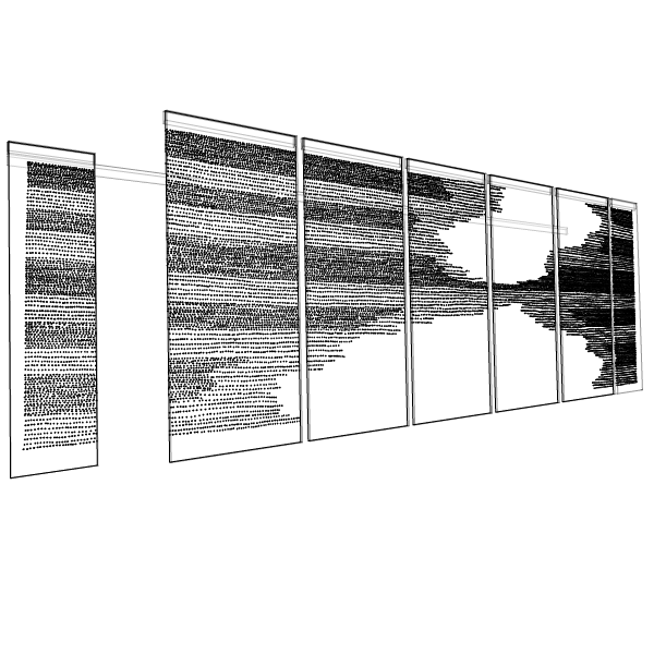
3. Create 3D Surface
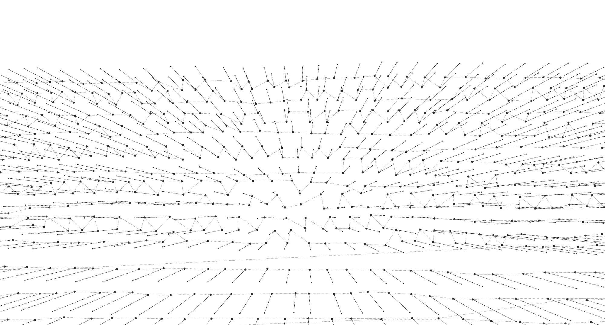
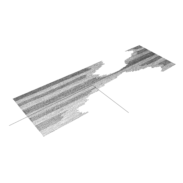
We designed a surface in Rhino that's purely aesthetic, using the original drawing as a guide. It’s a simple form that we hoped would showcase the power of digital fabrication without distracting from the original work.
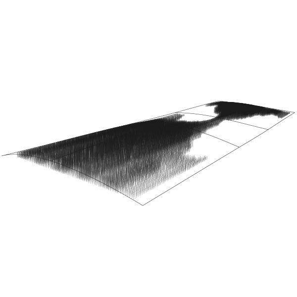
4. Extrude Dowels to Surface
A circle at each dot's centroid was extruded until it hits the 3D surface.
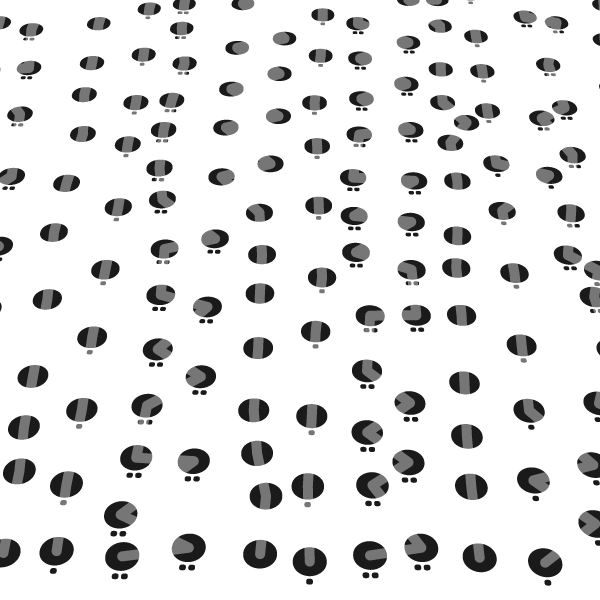
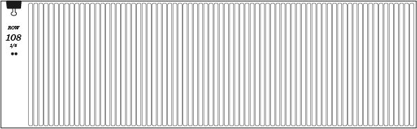
5. Find & Mark Rows
We needed a method of organizing the holes into rows to guide the installers. We designed a Grasshopper script that finds logical rows within the hand drawn pattern. The row’s zig-zag route only appears in the software creating the need for a breadcrumb trail. We used a dot, double dot, or no dot marking scheme which made it easy to identify and stay in your row during the installation.
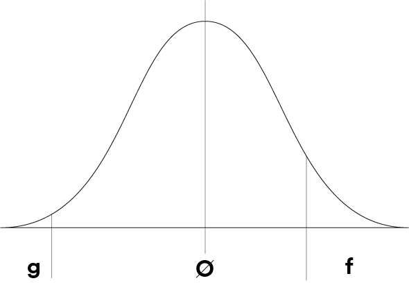
6. Hole Size
We did a statistical study of the dowel diameter variability to help us pick the best hole diameter. This ensures ~95% of the dowels would only need a light press fit during installation. Less than 1% would need glue (g), and 5% would require a heavy force to install (f).

7. Panel Machining
Each 4' x 8' MDF panel was painted, then machined on a ShopBot Alpha over a 7 day period. After pocketing the holes, we used a V-cutter to engrave the row markings.
8. Hang Panels
A French cleat was fitted to each panel which allowed us to easily hang the panels.
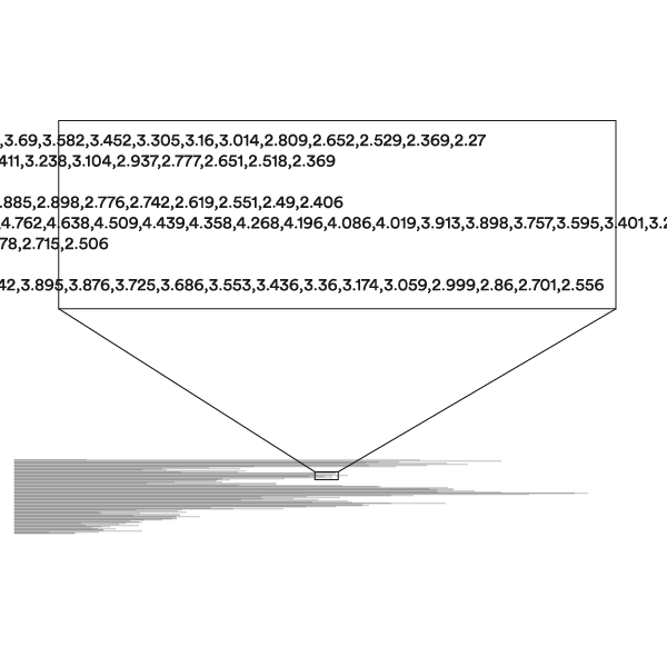
9. Export Dowel Lengths
Grasshopper was used to export the dowel lengths as a CSV file. Each row of the file contains a complete row of dowels.
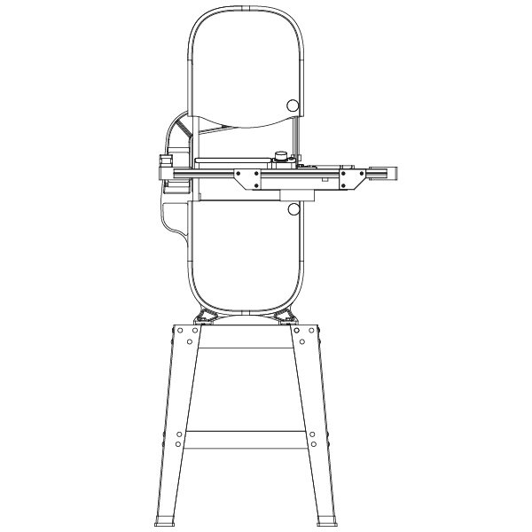
10. Cut Dowels to Length
The CSV file was loaded into Chop-Chop using an SD card and each dowel was cut to length.
11. Stage Dowels & Install
MDF trays were fabricated to help us stage each row during the install.